

The first step to understand a risk is to analyze the process behind. Enter oilfield water and SWD facilities.
There’s no question that owners of Saltwater Disposal -a.k.a. SWD- sites face a difficult task when trying to insure their properties. The discontent stems from a particularly dreary loss record. Many (most?) people call this market uninsurable. But I don’t think it's as clear-cut as it seems to be. There are hundreds of SWD facilities out there that have long operated without incidents.
Much confusion swirls around the actual reasons triggering the losses. But before digging into the risks, let's first understand what happens inside a facility.
SWD isn't very far from a cookie-cutter method. In essence, the process 1) removes the solids, 2) separates the residual oil and gas -and there's always some-, 3) disposes the remainder wastewater volume, 4) while the skim oil is sold away.
A facility hosts a number of tanks, piping, and pumps, and it's often unmanned. In general, it has none, or minimal, moving parts and it's designed for a set of conditions, i.e., flow rate, oil concentration, oil gravity, pH, solids content, etc.
Without being nitpickingly technical, the following figure depicts the main areas of an SWD site, where the plain vanilla process goes like this:
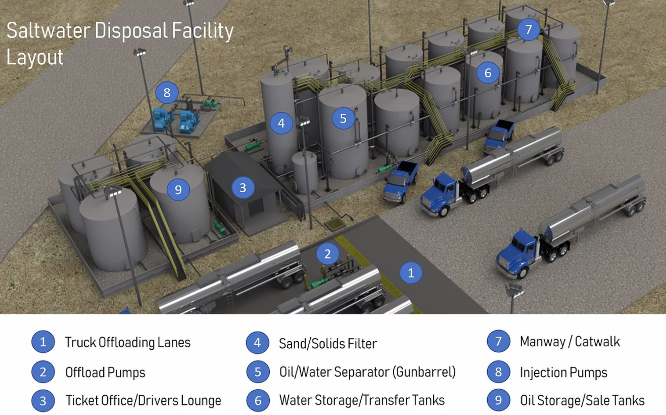
- Water arrives through pipeline gathering systems and through trucks. A large-diameter pipeline can gather water from multiple wells and customers along its path. Increasingly, abandoned oil and gas pipelines are being repurposed to transport wastewater.
Trucks, on the other hand, are more commonly used to transfer flowback water from new wells. - When water is trucked, the Offload Pumps transfer it into the facility.
- The Ticket Office handles the paperwork for truck drivers. This process is fully automated in many sites.
- The first treatment is to remove the solids in a Desander tank. This prevents further solid buildup downstream.
- Water then is taken to a vertical gunbarrel to separate oil and water. It has a typical capacity of 750-1,000 barrels and it can treat up to 10,000 barrels per day. At that rate, water is retained in the tank for about 2.4 hours -residence time-, allowing the oil to separate through gravity and be later skimmed.
- The treated wastewater without oil is stored in holding tanks, waiting to be injected downhole.
- The manway/catwalk is used for the very few instances when people are at the facility maintaining or inspecting the tanks
- The injection pumps draw water from the water storage tanks and inject it downhole through a saltwater disposal well.
- The skimmed oil is stored until being sold and periodically taken away with an oil tanker.
There are many variations to this typical layout, but the operating principles are the same across all SWD sites. Some facilities may include a breakout or free-water knockout tank at the receiving end of a pipeline feed.
For the sake of clarity and having looked at a myriad of videos on this subject, I find that the following makes a decent run at depicting the components and fluids flow at an SWD facility (no brand endorsement).
Process Upsets
When the process is operating within the design parameters, the water quality will be good, the injection well will operate with low maintenance costs, and most of the available oil and gas will be collected. As simple as it sounds, there can be several process issues and it is not uncommon for the conditions to be outside the design parameters. For instance, the input water volume can fluctuate greatly, especially when water is trucked. In addition, water quality varies and most times it comes with significant amount of oil and solids that do not separate. Some of the oil is emulsified, and some is coating the solids, sinking to the bottom of the tanks.
Much of the risk at an SWD site is due to the availability of flammable materials. Inside the tanks, the risk is a function of the amount of hydrocarbons, which greatly depend on the oil-water separation. Most facilities use a vertical gunbarrel, but here, however, is the kicker: this tank unit is designed to separate water from oil; not oil from water. When the water feed is higher than normal, the residence time inside the separator is lower, which can make the separation inefficient.
With poor separation, the problems can compound: Any contamination with light hydrocarbons downstream the gunbarrel will give way to an increasing concentration of volatile materials with flammable vapors on each holding tank. This in turn reduces the flash point of the mixture, and increases the risk of fire across the facility. Most times, the effective flash point is higher than the maximum storage, ambient, and rundown temperatures, and an ignatable quantity is less likely to be present, unless of course, an electrical spark occurs (hello lightning!).
Improving hydrocarbon separation is one of the main reasons why newer facilities avoid vertical gunbarrels. These, along with the desander tank and associated piping are being replaced by a new horizontal fixed-roof gunbarrel design, which is more efficient in the oil separation and it also allows online solids removal without opening or entering the unit. Moreover, smaller water storage tanks are in turn being replaced by few large capacity units.
While we're here:
The economies of the SWD business are built on: 1) recovering as much oil as possible which is then sold, and 2) its ability to inject wastewater downhole at a high flow, charging ~$0.50 for every barrel of water treated. For areas that have the same geology, one would expect to record similar injection pressures. But the actual data is a mixed bag. In some areas, SWD wells are reaching their disposal capacity, i.e., Eddy County in New Mexico (Permian Basin).

On Tanks, Venting, and Other Safety Matters
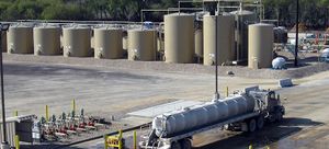
Tanks are the heart of an SWD facility and they come in many flavors. The vast majority -if not all SWDs- have unheated, fixed self-supported cone or flat roof welded designs, which you have to admit, is a spectacular term for vertical steel cylinders with a permanently attached roof.
In the universe of tank designs (Figure below), it isn't the safest alternative for emission control, but they are quite cost effective.
Smaller water-holding tanks are usually built to API Spec 12F, "Specification for Shop-welded Tanks for Storage of Production Liquids". Very large water-holding tanks are built to API Spec 12B, "Specification for Bolted Tanks for Storage of Production Liquids". On the other end, oil-holding tanks should be built to API Std 650, "Standard for Welded Tanks for Oil Storage".
It's very rare, very rare, to find an SWD facility where tanks have built-in fire-suppression systems. There must be one out there, but as the song goes, I just haven't found what I'm looking for.
On each tank, the space between the liquid surface and the underside of the roof is filled with vapor, which is usually flammable because the oil-water-gas separation is never 100% efficient. This vapor expands/contracts with liquid movement, weather changes, temperature changes, and many multiple circumstances resulting from equipment failures and operating errors.
On SWD, there isn't enough gas to make a case for recovery. As the vast majority of the facilities aren't equipped with environmental controls to capture fugitive emissions, the vapor is vented to the atmosphere. But even venting needs to be engineered even if there's no regulation mandating the adoption a relevant standard such as API Std 2000, "Standard for Venting Atmospheric and Low Pressure Storage Tanks".
Ideally, each tank should be fitted with a Pressure/Vacuum PV valve to manage normal operational activity and atmospheric changes. But this isn't always the case: Many tanks just have open vents and don't even have flame arrestors.
Some SWD sites have common discharge headers, piped away from the tank battery. Of course, devil's on the details; they should be protected against mechanical damage, fitted with ran caps or drains, avoid liquid traps, and maybe use flame arrestors.
A word on flame arresters per API Std 2000:
Its use of this in an open vent line or on the inlet to the pressure/vacuum valve is an effective method to reduce the risk of flame transmission. But it introduces the risk of tank damage from overpressure or vacuum due to plugging if the arrester is not maintained properly. Either way, it increases the pressure drop of the venting system. There's a belief that PV valves have a potentially inherent flame-arresting capability, though recent testing disproves this hypothesis for the tested conditions.
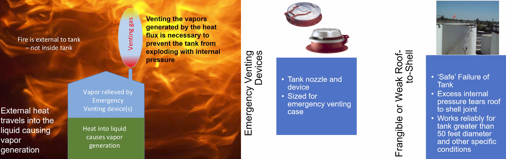
Tanks should also be designed for emergency venting. This can be achieved by installing specialized devices or by having a weaker roof-to-shell attachment (a.k.a frangible roof seam). In the event of facility fire or other abnormal conditions, tanks without these risk controls can be ejected like rockets, rupturing or separating at the shell-to-bottom seam.
I have on purpose not discussed the issues associated with material selection for tanks. We'll get there on another post.
Share, follow, stay tuned for more!